
CNC Machining China Factory: What Tolerances and Surface Finishes Are Realistic?
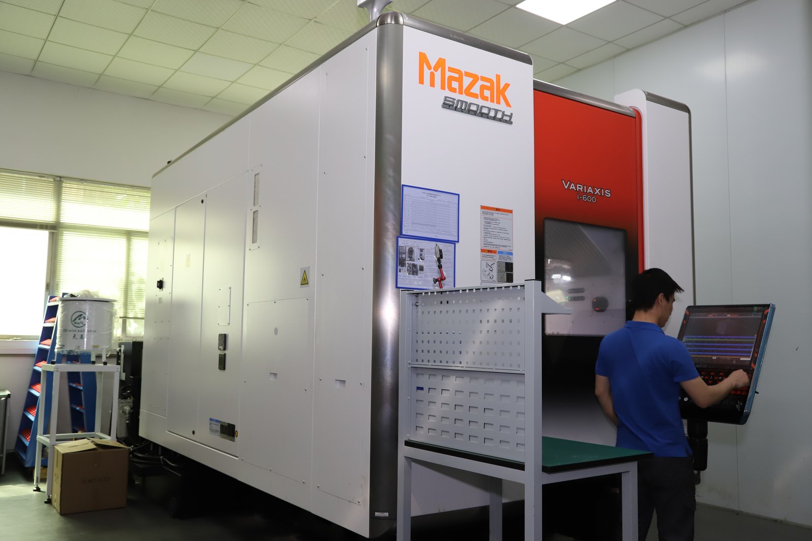
A factory's tolerance story is written in its machine list before a drawing ever arrives. The machines decide which processes live under one roof, the measurement equipment decides which tolerances can be proven rather than promised, and the process discipline decides whether the band holds across a run or drifts into rework. This guide is the buyer's reality check for a CNC machining factory in China — the tolerance bands and finish ranges a real production floor holds consistently, how to read a machine list and a measurement lab for what they actually promise, which features and materials move a part between process families, and how to state tolerance and finish on the drawing so the quote matches the part you need.
What does a factory's machine list tell you about the tolerances it can hold?
Tolerance is a process fact before it is a drawing fact, and the process facts live in the machine list. A factory with depth in three-axis machining can hold ±0.003 mm on prismatic features it can reach in one setup; a factory that adds 4-axis and 5-axis capacity can hold positional relationships between features on different faces, because the part rotates to present each face to the cutter without being re-clamped. The axis count is not a marketing number; it is the physical answer to which tolerances are reachable in one reference frame.
Read the machine list for depth in the process your part needs, not for the headline total. The factory behind this site runs 100+ production machines — 50+ three-axis, 20+ four-axis, and 20+ five-axis machining centers, plus 25+ lathes and 7+ grinders — across a 6,800 m² floor. A list like that supports a schedule: when your job needs a 5-axis machine, several sit open rather than one queued behind unrelated work. The schedule is where a tolerance becomes real, because a tolerance that waits weeks for the one machine that can hold it is a tolerance that has already cost you your launch date.
The grinding count matters most for tolerance buyers. Grinding is the second family in the tolerance ladder — ±0.002 mm against turning and milling's ±0.003 mm — and a factory that owns 7+ grinders can keep a ground feature in-house instead of routing it to an unnamed partner. Ask where each stage of your part's process happens; the answer tells you whether the tolerance chain stays inside one quality system or crosses into a vendor's. The factory page on this site is the machine list and floor plan, and it is worth reading the same way a buyer reads a drawing — for what it commits to, not what it hopes.
Which tolerance bands does a factory hold consistently, and how are they proven?
The realistic starting point for a CNC machining factory in China is a two-band ladder. Standard milling and turning work holds ±0.003 mm on critical features, and precision grinding reaches ±0.002 mm for bearing seats, seal faces, and roundness-critical surfaces. Those are the bands the floor holds routinely, not peak capabilities quoted for show, and the difference between the two bands is a process family, not an attitude.
| Process | Tolerance band | Typical finish as-cut | Features it serves |
|---|---|---|---|
| CNC milling (3/4/5-axis) | ±0.003 mm | Ra 1.6–3.2 µm | Housings, brackets, plates — prismatic features |
| CNC turning and mill-turn | ±0.003 mm | Ra 1.6–3.2 µm | Shafts, fittings, mixed round-and-prismatic parts |
| Precision grinding | ±0.002 mm | Ra 0.8 µm and finer | Bearing seats, seal faces, roundness-critical surfaces |
| ISO 2768 general block | ±0.1–0.5 mm by size range | — | Non-critical dimensions left to the drawing's general note |
A quoted tolerance is only as real as the measurement that backs it, and the measurement equipment is the second half of the factory's story. Dimensional callouts on critical features should be verified on coordinate measuring machines, and finish should be read on a surface-measuring instrument that reports an actual Ra value. The quality page on this site names the instruments: Hexagon GLOBAL S CMMs, a KEYENCE VK-X3000 laser microscope, and a SURFCOM 1800D, on a calibration schedule against traceable standards. A factory that names its instruments is one whose tolerance claims can be checked; a factory that only names its tolerances is asking you to take the measurement on faith.
Which tolerance is realistic on which feature?
Within the ±0.003 mm band, the realistic expectation varies by feature, because each feature fails in a different place. A short, stiff bore or diameter holds the band without drama. A positional relationship between features on different faces — a bore pattern that must land relative to a machined edge — depends on the setup, and it is only physically honest if the part is cut in one reference frame. That is where the axis count earns its keep: a 4-axis or 5-axis program holds the relationship because the part rotates to present each face to the cutter, while a part re-clamped to reach another face stacks error onto the very feature the assembly needs.
Roundness and concentricity on turned features follow the same rule. A shaft that rotates in a bearing has to be round, and a bore that receives a mating part has to be concentric to the outside diameter. Those form relationships are created by the setup — a part turned in one clamping holds them, a part re-chucked to machine the other end reintroduces the misalignment. On mixed parts, mill-turn earns its place by machining turned and milled features from one datum, removing the handoff error between a lathe and a mill.
The features that cannot honestly hold the tight band are the ones geometry defeats before the process starts. A thin wall deflects under the cutter unless the fixture backs it; a deep pocket demands a long-reach tool that wanders; a long slender shaft — length-to-diameter ratio above about 3:1 — deflects under its own cutting forces. On those features, the realistic expectation is a looser profile tolerance plus a support plan, not a tight callout that turns the job into a sorting exercise. The drawing that separates the rigid features from the compliant ones is the drawing that quotes fast and ships first-pass.
Which surface finish is realistic from a machining factory?
Surface finish is stated as an Ra value, and the values a machining factory delivers consistently fall in a narrow range. As-cut milling and turning land around Ra 1.6–3.2 µm — the natural finish a sharp tool leaves at normal feeds. Ra 0.8 µm takes a fine feed or a light finishing pass, still on the machining floor. Ra 0.4 µm and finer moves the feature to precision grinding or honing, and Ra 0.2 µm and finer means polishing or lapping — each step down the ladder buying a slower process and a longer schedule.
| Finish target | How it is produced | What it costs the order |
|---|---|---|
| Ra 3.2 µm | Rough/finish milling or turning in one pass | Nothing extra — the as-cut default |
| Ra 1.6 µm | Finish pass at a slower feed | A little extra machining time, usually free of schedule impact |
| Ra 0.8 µm | Fine machining or light grinding | A finishing step with its own setup and inspection |
| Ra 0.4 µm | Precision grinding or honing | A grinding setup; the feature moves to a slower process |
| Ra 0.2 µm and finer | Polishing or lapping | A dedicated finishing process — reserve for the function that needs it |
Two finish traps cost factory buyers the most. The first is specifying Ra 0.4 µm on a surface that only needs to look acceptable — the shop can hold it, but the feature quietly moves to grinding for no functional gain. The second is confusing a coating with a finish. Plating and anodizing change the surface chemically and add a layer that shifts the final dimension; they do not reduce the Ra of the machined surface underneath, and on a plated thread or journal the part must be machined with plating allowance so the coating brings it to final size. State the machined finish and the coating as two separate requirements, and the drawing stays unambiguous.
How do material and factory capability interact?
Material moves the tolerance and finish equation on every factory floor, because machinability sets the speed, the tool wear, and the heat in the cut. Free-machining grades — 12L14 steel, 303 stainless, brass, aluminum 6061 — cut cleanly with light forces and hold a tight band without drama. The other end of the ladder — 304 and 316 stainless, titanium, the nickel alloys — holds the same band on rigid features but cuts slower, deflects more, and costs more in tooling and time. None of this is the factory's fault or the material's; it is the physics of the cut, and a factory that quotes it honestly is a factory you can plan around.
Factory capability interacts with material in one way buyers should check explicitly: does the factory run the difficult materials in-house, or does it route them to a specialist? Titanium and the nickel alloys demand rigid machines, fresh tooling, and disciplined coolant control; a factory with experience on those materials has the fixtures and the feeds tuned. A factory that routes them out is adding a vendor handoff to the tolerance chain. Ask which materials the floor actually runs daily, and match that to your part's material before you commit.
Heat treatment is the third axis of the same interaction, because it moves the finished dimensions. A part machined in a soft state and hardened afterward — 17-4 PH aged to H900 or H1150, alloy steel quenched and tempered — can move a few micrometers in the treatment. The factory's tolerance promise applies to the finished part, which means the sequence — rough, heat treat, finish — has to be planned so the last operation lands inside the band. A drawing that names the material condition is a drawing the factory can schedule correctly; a drawing that stops at the alloy name leaves the most consequential part of the process unwritten.
How do you read a factory's quality story for the tolerance it can prove?
A factory's quality story is only as convincing as its measurement and process evidence, and there are three things to look for. First, the measurement equipment: CMMs for dimensional callouts, a surface instrument for finish, XRF for material grade — named, not implied. Second, the process evidence: SPC data with a stated Cpk target, because capability is what turns "the first article measured right" into "the process stays right." On the floor behind this site, the SPC record shows Cpk = 1.851 on a representative length characteristic of 76.1–76.5 mm against an initial-study target of Ppk ≥ 1.67. Third, the incoming-material gate: every lot XRF-checked against its mill certificate before any bar is cut, because a substituted alloy passes every dimensional check and still fails.
Read the tolerance band before you read the index. Cpk is a ratio of the tolerance band to the process spread, not an absolute measure of accuracy. The figure above was recorded on a length characteristic with a 0.4 mm band (76.1–76.5 mm) — wide by design. Hold the same process spread against a ±0.005 mm feature and it fails outright. Ask for the band, the subgroup count and the sampling window on every capability number a supplier quotes.
The certificates complete the picture, and they should be read for scope, not for the logo. ISO 9001:2015 (116024/A/0001/UK/En), IATF 16949:2016 (131941/A/0001/SM/En, with product design excluded under Clause 8.3 as a build-to-print manufacturer), and ISO 14001:2015 (116024/B/0001/UK/En) describe a quality system; they do not replace the measurement and process evidence. A certificate tells you the system exists; the Cpk chart and the calibration records tell you it works. Ask for both, and you will know which factory you are dealing with. The DFM and process guide on this site walks the full drawing-to-quote path; this page is the tolerance-and-finish layer, the part of the review that maps each feature to the process that will hold it.
How do you state tolerance and finish so the factory quotes the part you need?
A drawing that states tolerance and finish cleanly is a drawing a factory can quote in one pass and machine without asking. The discipline runs in four short lines. First, put an ISO 2768 general note on the drawing — "ISO 2768-m unless otherwise noted" — so every unmarked dimension is unambiguous. Second, call out the tight tolerances only on the functional features, and name the process each one implies: the milled bore pattern, the turned bearing journal, the ground seal face. Third, state the surface finish in Ra where it matters, with the feature named, and leave the cosmetic surfaces on the general note. Fourth, if a coating is involved, say so as a separate line with its allowance, because the machinist needs to cut to the pre-coat dimension.
State finish in Ra, not in adjectives. "Fine finish" and "smooth" are negotiable in a way that Ra 0.8 µm is not; the number is what the shop can measure, quote against, and prove on the inspection report. The same rule applies to tolerances: give the band, not the sentiment. A drawing that says ±0.003 mm on the bearing journal and ISO 2768-m everywhere else has told the machinist exactly which dimensions matter and which are free to run, which is precisely the information a fast, accurate quote is built from.
If the production part carries the same features, the prototype should carry the same numbers. A prototype with looser tolerances than production validates the geometry but not the process, and the point of a first article is to prove the process that will make the real parts. With a minimum order of one piece, a factory can run the first article, measure it against the drawing, and let that measurement gate the production release, which is how a tolerance conversation becomes a process you can audit.
Frequently Asked Questions
What tolerance can a CNC machining factory in China realistically hold?
Milling and turning hold ±0.003 mm on critical features, and precision grinding reaches ±0.002 mm for bearing seats and sealing faces. The realistic expectation is tighter on rigid, well-supported features and looser on thin walls, deep pockets, and long slender shafts.
How do I know a factory can prove the tolerance it quotes?
Ask what measures the parts and how recently the instruments were calibrated. On the floor behind this site, Hexagon GLOBAL S CMMs handle dimensional checks, a SURFCOM 1800D reads surface finish, and the instruments sit on a calibration schedule against traceable standards, so a quoted tolerance has a measurement behind it.
What does the machine list tell me about a factory's tolerance capability?
Everything. The axis count tells you which positional tolerances are reachable in one setup, the lathe count tells you how turned work is scheduled, and the grinder count tells you whether a ±0.002 mm feature stays in-house. A factory with depth in the process your part needs is a factory whose tolerance you can trust.
What surface finish should I expect as-cut on a machined part?
Standard milling and turning leave around Ra 1.6–3.2 µm. Ra 0.8 µm takes a fine feed or a light finishing pass; Ra 0.4 µm and finer moves the feature to precision grinding or honing; Ra 0.2 µm and finer means polishing or lapping.
Is plating or anodizing a way to improve surface finish?
No. Plating and anodizing are coatings — they change the surface chemically and add a layer that shifts the final dimension, but they do not reduce the Ra of the machined surface underneath. On a plated thread or journal, the part must be machined with plating allowance so the coating brings it to final size.
Which features cannot hold the tight tolerance band?
Thin walls deflect under the cutter unless the fixture backs them; deep pockets demand long-reach tools that wander; long slender shafts deflect under their own cutting forces. On those features the realistic expectation is a looser profile tolerance plus a support plan, not a tight callout on an unsupported surface.
How does material change what a factory can hold?
Free-machining grades like 12L14 steel, 303 stainless, brass, and aluminum 6061 hold a tight band cleanly. 304 and 316 stainless, titanium, and the nickel alloys hold the same band on rigid features but cut slower, deflect more, and cost more. Heat treatment after machining moves the finished dimensions, so the material condition belongs on the drawing.
What records should a factory ship with the parts to prove the tolerance?
CMM reports on critical dimensions with the method named, SPC evidence at Ppk ≥ 1.67 at the initial study on key characteristics and Cpk ≥ 1.33 on general characteristics. Capability is reported per characteristic: every report names the feature, its tolerance band, the sample size, the sigma method, and the study window., material certificates with the XRF verification behind them, and finishing records. Specify the document set in the RFQ so the quote prices it, and check the delivery against it in the same order every time.
Need a realistic tolerance and finish read from the factory that would make your parts?
Send the STEP or IGES model and the toleranced 2D drawing to [email protected] or call +86 13126536955. The reply will include a design-for-manufacturing review, the machine route the part will take across the floor, an honest tolerance and finish read on each feature, and a quote tied to the process the drawing actually requires.